Custom Data Visualization with Python
Quick guide on how to set up various graphs using Matplotlib in Python
MQTTRover is a custom-built, two-wheeled robot controlled via an Android app and powered by an MQTT broker, Node-RED, and Python. Designed for hands-on learning, it features a 3D-printed body housing two motors, a motor control board, a battery pack, and a Raspberry Pi for command processing.
The Android app allows users to control the robot's movements and view its camera feed, sending commands through MQTT. Node-RED, running on the Raspberry Pi, listens to these messages and executes movement commands via a Python script. This project integrates software and hardware, providing a practical experience in robotics, programming, and CAD design.
For my personal project, I created a custom two-wheeled robot called MQTTRover, powered by MQTT, Node-RED, Python, and a custom-built Android app. My goal was to gain hands-on experience in robotics and electronics by tackling something new and challenging. I especially wanted to improve my skills in 3D printing, CAD, and essential tools like MQTT, Node-RED, and Python, which are widely used in IoT and robotics.
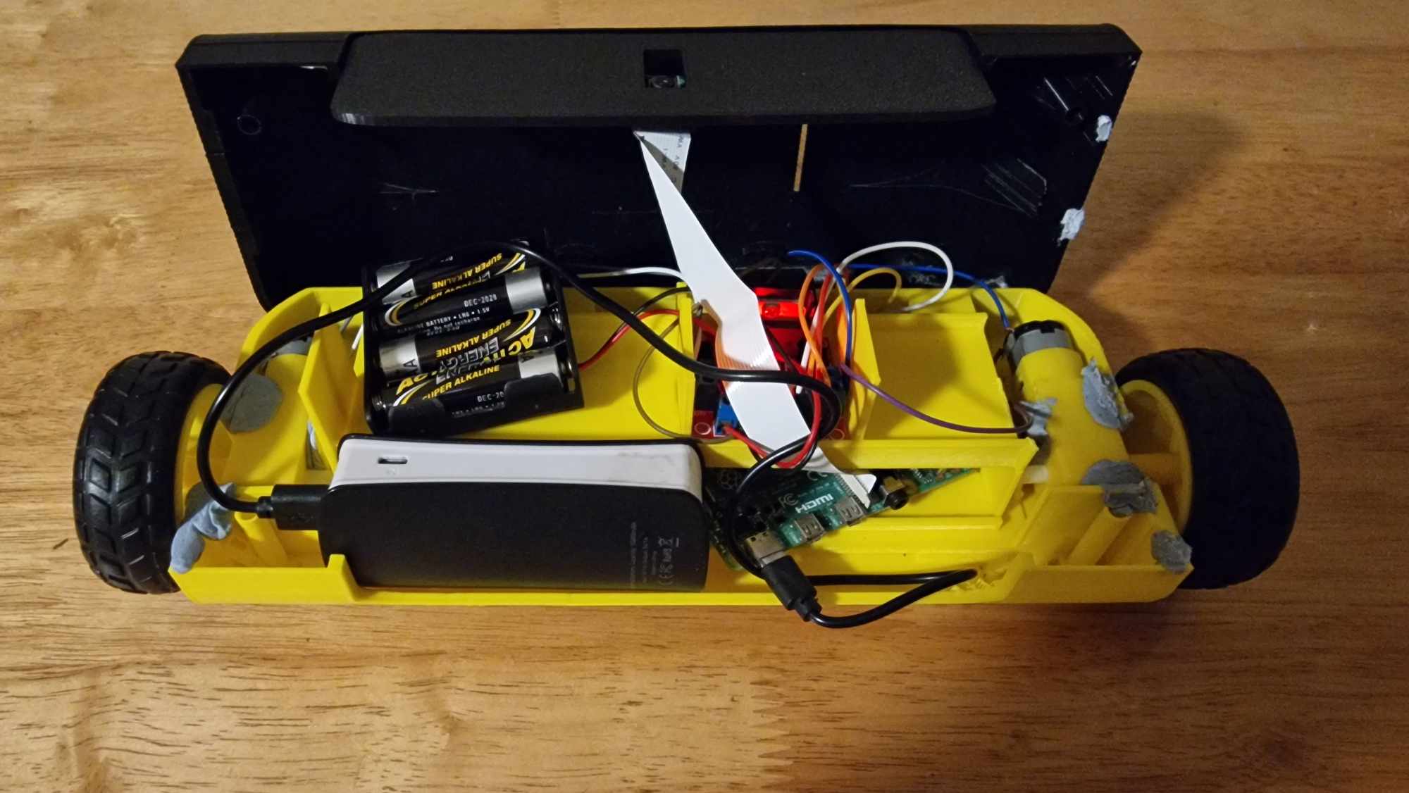
I designed MQTTRover in CAD software, then 3D-printed its body in three separate parts. For the internal components, I used two motors connected to a motor board powered by a battery pack, and linked this board directly to a Raspberry Pi for control.
To operate the robot, I created a custom Android app that lets users control movement and view the Raspberry Pi camera attached to the robot. The app sends control messages to an MQTT broker, based on user input. Node-RED, running on the robot's Raspberry Pi, listens to these MQTT messages and passes the commands to the robot through a custom Python script.
This project offered a great way to explore the integration of hardware and software in robotics. It challenged me to experiment, troubleshoot, and develop creative solutions, making it a rewarding experience for building my skills and knowledge.
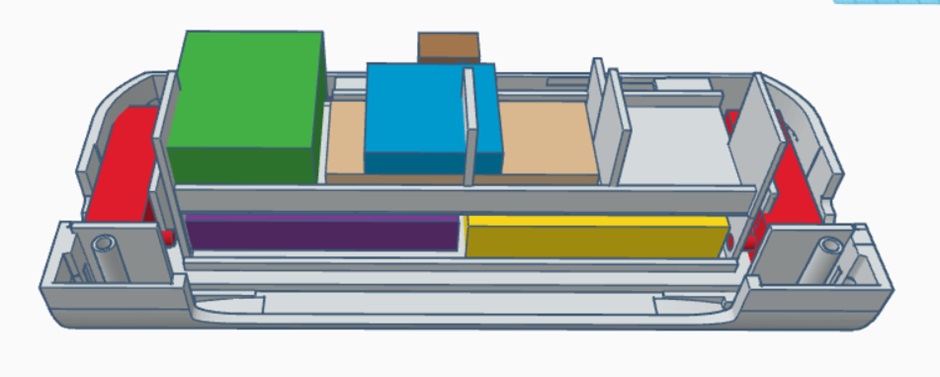
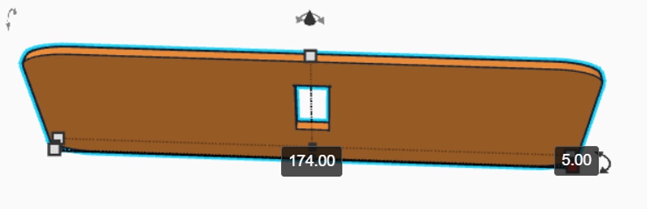
To create the 3D structure of MQTTRover, I used TinkerCad, a free, web-based CAD tool. I started by designing the bottom section of the robot, where I needed to carefully place each component. I took measurements for all the parts I planned to use, including the Raspberry Pi, motors, and battery pack, and then made simple 3D reference models of each.
This helped me make sure there was enough space for each part and kept the layout efficient. I also added some open space at the back for the wiring, allowing everything to connect smoothly.
This step was the hardest part of building MQTTRover's 3D body. It required careful planning to fit all the parts correctly without wasting space. In fact, I had to go through three different design attempts and prototypes before I got a version that worked well.
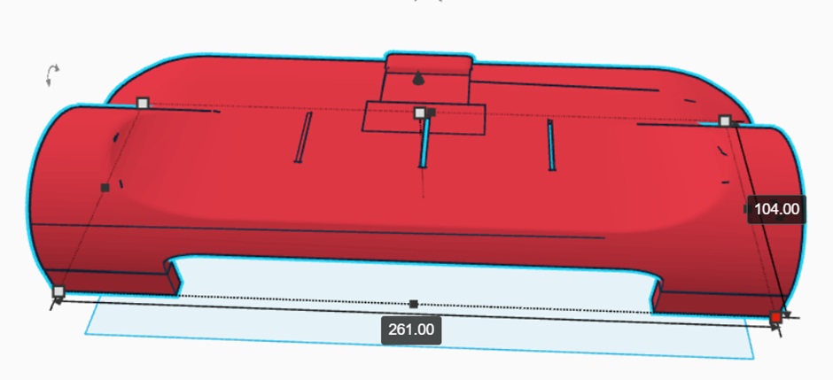
The top part of MQTTRover was much easier to design compared to the bottom. My main focus here was to align it perfectly with the bottom section so that both parts could fit together seamlessly. I also made sure there was enough headroom for all the components inside. This top part didn't need as much detailed planning since it mostly served as a cover and allowed the necessary space for everything below.
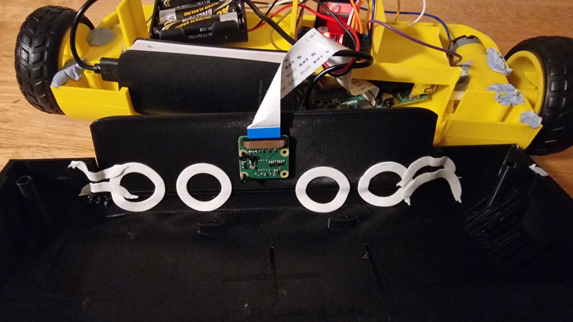
The middle section was straightforward as well. Its main purpose was to hold the Raspberry Pi camera in place, so I designed an opening specifically for the camera lens. I made sure this middle section was the right size to fit neatly between the top and bottom parts of the robot. This way, the camera would have a clear view without obstructing any other components.
Designing each part of MQTTRover's 3D structure was a valuable learning experience, as it required careful planning and precision to ensure every component fit together smoothly. From the complex bottom section to the simpler top and middle sections, each piece needed thoughtful design and multiple adjustments to create a functional and compact robot body. Through this process, I gained hands-on skills in CAD design and problem-solving, setting a solid foundation for future improvements and additions to MQTTRover.
To bring MQTTRover to life, each part needed to be wired and connected so the Raspberry Pi could control the motor board, and the motor board could power and manage the motors. This setup also required connecting the battery pack to power the motor board and using a power bank to keep the Raspberry Pi running smoothly.
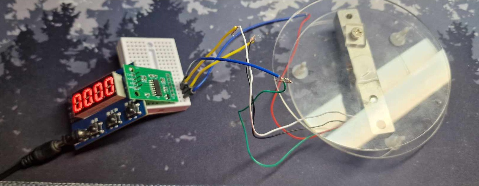
I started by attaching the jump wires from the motor board to specific pins, carefully matching each wire to the correct pin address. This step was important for ensuring I could later connect these wires to the Raspberry Pi without any mix-ups. I also connected additional wires to the appropriate pins for the motors to ensure they would respond to commands from the motor board.
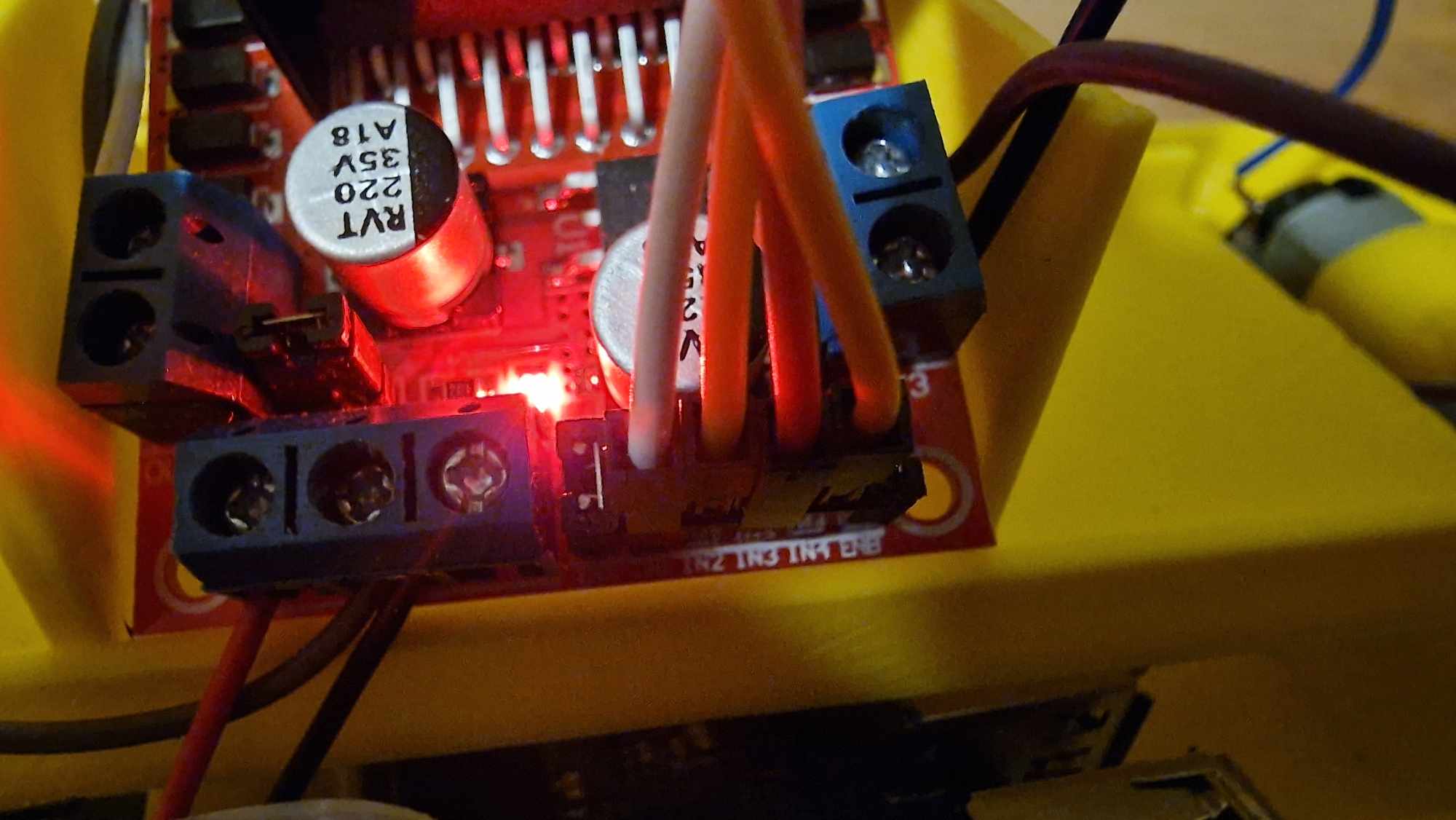
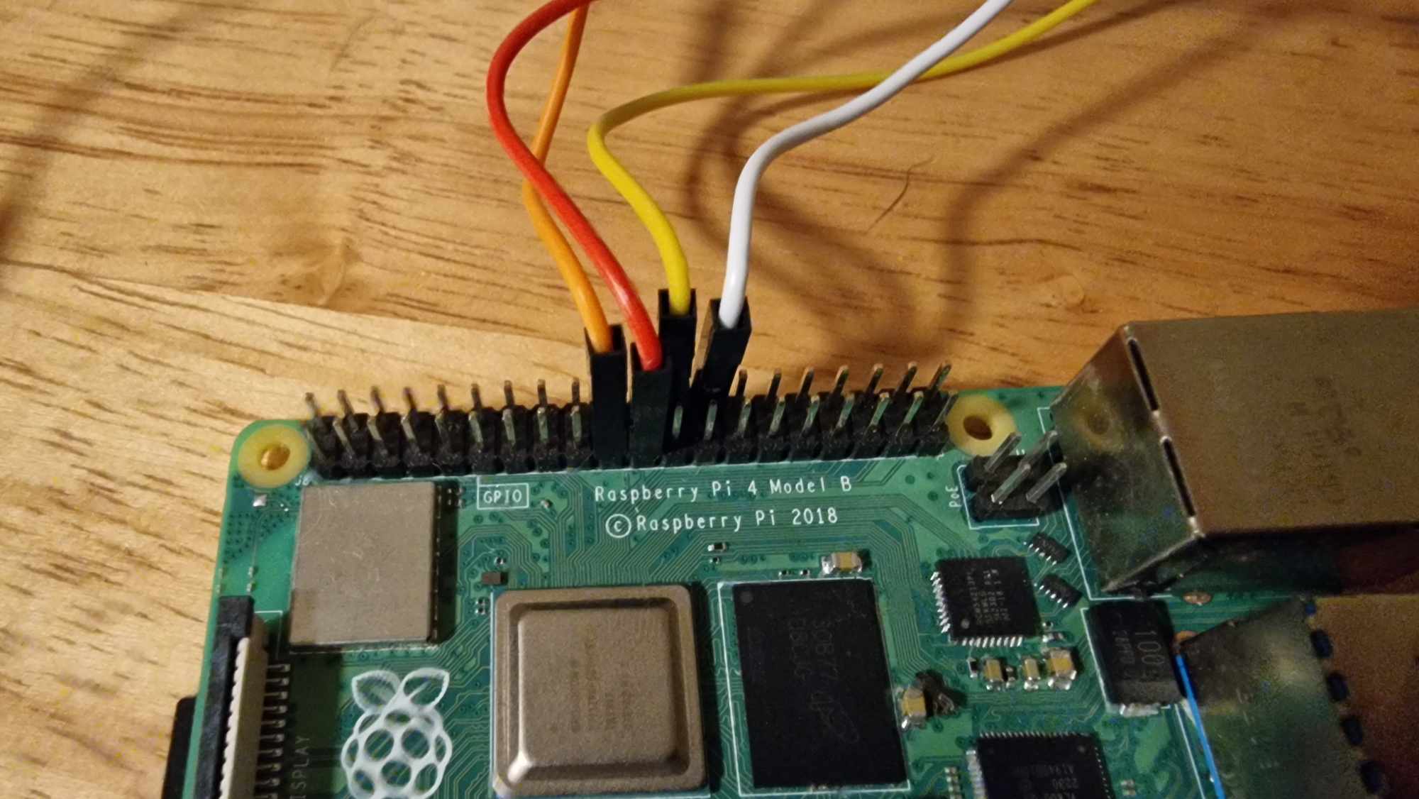
After preparing the motor board, I connected the jump wires from the board directly to the Raspberry Pi pins. These connections let the Raspberry Pi send signals to the motor board, controlling how the robot moves. Making sure these connections were firm was important to avoid any issues during movement.
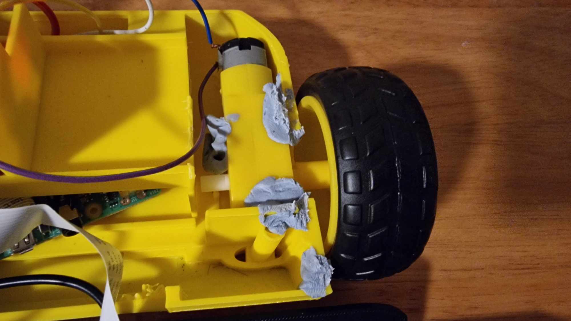
Next, I placed the motors into their designated spots in the robot body. To keep them steady and prevent any shifting while the robot was in motion, I used small amounts of blue tack. This extra support helped the motors stay securely in place, making the robot more reliable when moving.
For the camera, I attached the Raspberry Pi camera module to the middle part of the robot and connected it to the Raspberry Pi. I used double-sided tape to secure the middle and top sections together, adding extra stability and making sure everything stayed connected as the robot moved around.
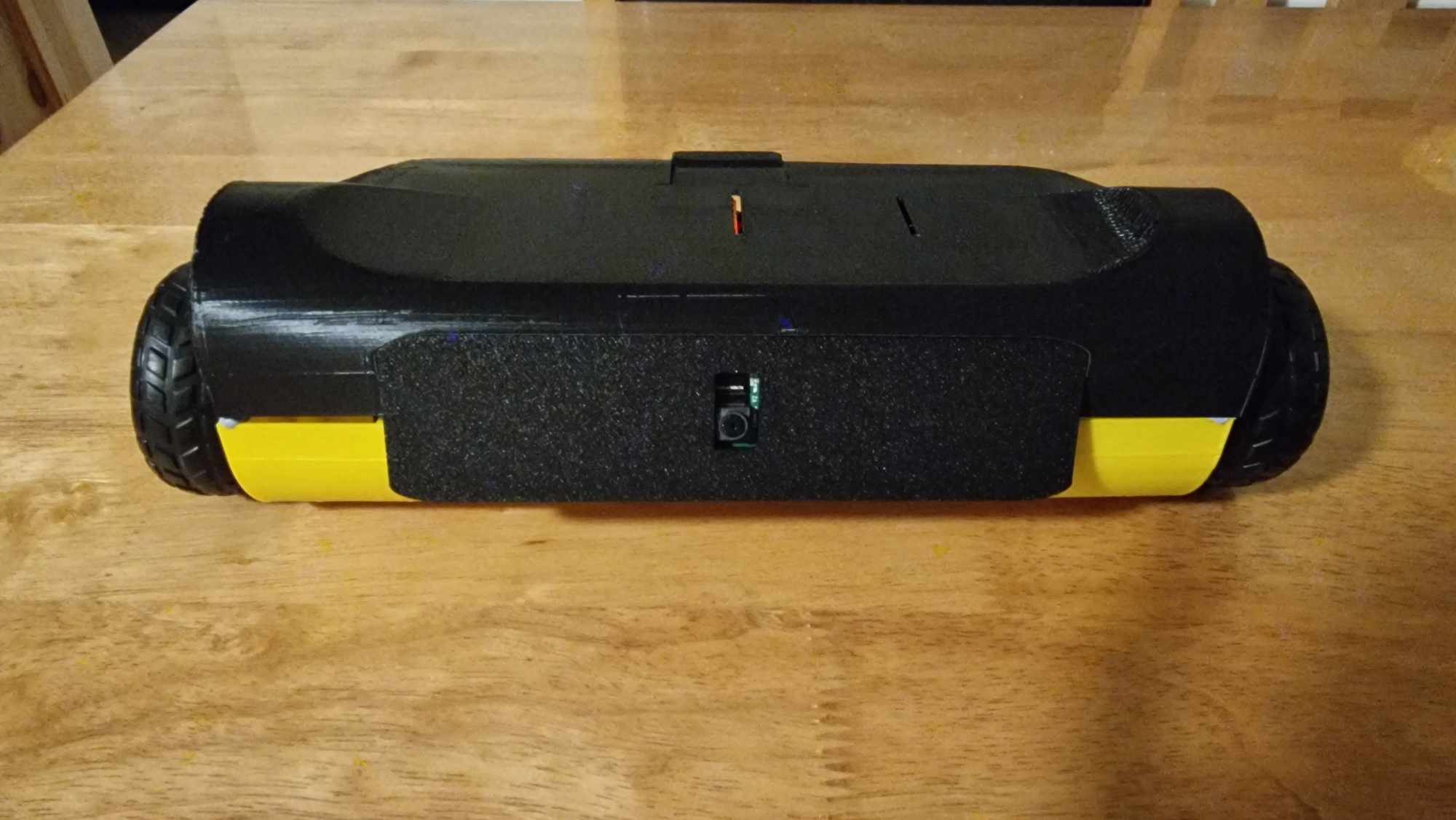
Finally, I assembled all the main parts, including the Raspberry Pi, motors, and battery packs, following the layout I had planned in TinkerCAD. This careful assembly made sure each component fit together as intended, giving the MQTTRover a sturdy build and setting it up for smooth operation.
Assembling the physical components of MQTTRover was a detailed process that brought together all the planning from the CAD design into a functional robot. Each step, from wiring the motor board and Raspberry Pi to securing the motors and camera, required attention to detail to ensure everything fit and operated smoothly. This hands-on assembly process reinforced the importance of careful planning and setup, giving MQTTRover a solid and reliable structure. Now, with all components in place, the robot is ready to perform as designed and paves the way for future improvements.
To bring MQTTRover to life, I designed a software system to handle all control functions, using MQTT, Node-RED, and Python to manage internal communication. My idea was to have MQTT act as the message receiver, with Node-RED waiting to catch these messages and pass them along to a Python script that directly controls the robot's movements.
To send the control messages, I developed a custom Android app with a simple interface. The app includes directional buttons, forward, backward, left, and right, as well as a section to view the live camera feed from the robot. When a user presses a button, such as "forward," the app sends a message to MQTT. Node-RED picks up this message and triggers the Python script to make the robot move accordingly. This system allows for real-time control and feedback, making MQTTRover both interactive and responsive.
Previously, I had built an Android app to scan nearby Wi-Fi access points, and completing that project was incredibly helpful in developing this new app to control MQTTRover. Using what I learned, I was able to create a simple yet effective custom application for controlling the robot.
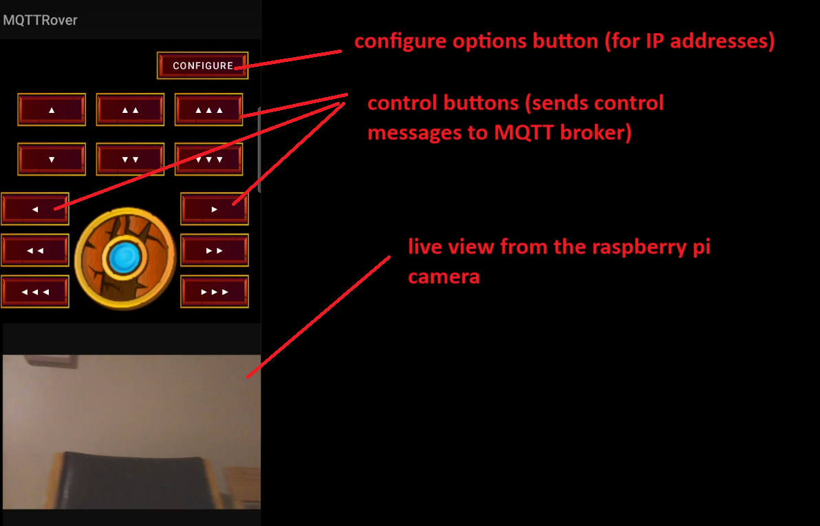
The app has a set of basic directional buttons: forward, backward, left, and right, allowing users (or me) to easily move the robot in any direction. I also included a view for the live camera feed, so users can see what the robot "sees" in real time.
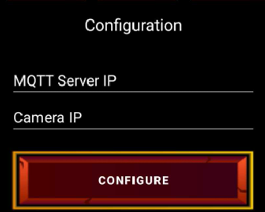
To make the setup more adaptable, I added a "Configure" button, where users (or myself) can enter the IP addresses for the MQTT broker and camera feed. This configuration option was essential in case the IP addresses ever need to be updated.
Designing and building the Android app for MQTTRover was a rewarding experience, allowing me to put my skills into practice and refine the robot's control system. The app's straightforward interface, with directional controls and live camera feed, made the robot easy to operate. Adding a configuration option also added flexibility, ensuring that the setup could be adjusted as needed. Overall, this project not only strengthened my skills in Android development but also provided valuable insights into integrating hardware and software for real-time control.

Setting up the MQTT part was straightforward. I installed a basic Mosquitto MQTT broker on the Raspberry Pi and created a topic structure for the robot's control system, using the topic "robot/control." The Android app publishes MQTT messages to this topic to send movement commands.
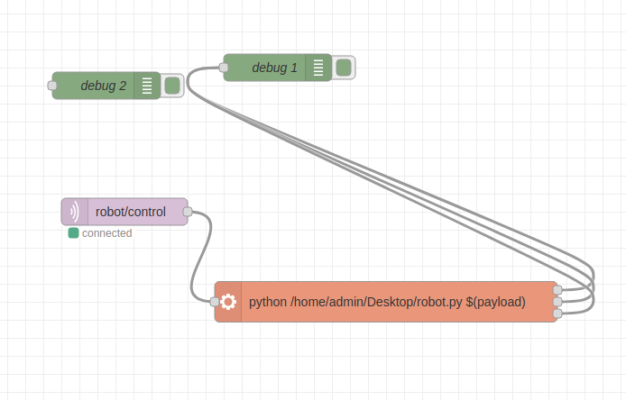
For Node-RED, I used an MQTT IN node to listen for any incoming messages on the "robot/control" topic. I then created a simple function to extract the message and used an EXEC node to pass this message as a variable to the Python script, enabling the robot to respond to commands in real-time.
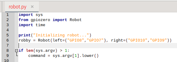
The Python script itself was relatively simple. I started by importing the necessary libraries and initializing the robot's motors on specific GPIO pins assigned to the left and right motors.
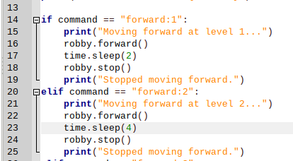
The script uses basic if-checks to determine the movement based on the incoming message. For instance, when a user sends a command from the app, the script checks the message and makes the robot move forward, backward, left, or right accordingly.
Designing the code structure with MQTT, Node-RED, and Python brought together each part of the MQTTRover's control system, making it responsive and straightforward to manage. Setting up MQTT as the communication layer, using Node-RED to process messages, and controlling movement with Python allowed for a clear and efficient flow of commands. This approach made the robot easy to control and adaptable for future updates, providing a solid foundation for future enhancements.
This project taught me a lot about robotics, from designing the 3D model to developing the app and configuring the software tools like MQTT, Node-RED, and Python. It took several attempts to get the 3D model right, set up the app functions, and fine-tune the software configuration. But with the experience I've gained, creating the next version will be much smoother.
One main takeaway was that the final robot was heavier and larger than necessary, which made its movement slower and less agile. In the next version, I'll focus on reducing the overall weight and size, which should improve mobility and make the robot more efficient.
For the internal components, I worked with what I had available, but I plan to upgrade for the next version. I'll use a proper rechargeable 18650 battery pack to power the Raspberry Pi and add an ultrasonic sensor to help the robot detect obstacles and avoid collisions. Additionally, I'll add switches to control the power for both the motor board battery pack and the Raspberry Pi, which will make managing power easier and add useful new features.
Overall, I've learned a lot from this project. Each challenge provided valuable insights, and now I feel more confident in applying these lessons to improve and build on MQTTRover in future versions.